


Hardware Projects
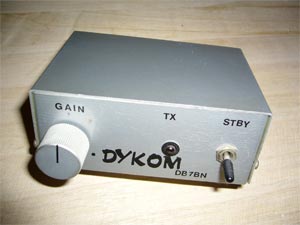
speech processor
One of my first amateur radio projects was the construction of a dynamic compressor in 1976. This small additional device is looped into the microphone line and gives the voice a higher "assertiveness" during SSB operation. Today, this technology is already built into the tranceivers.


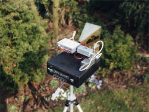
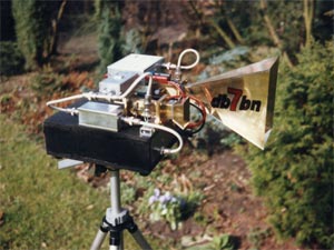
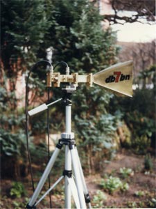
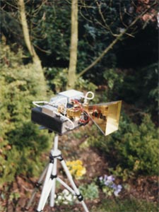
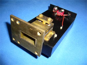
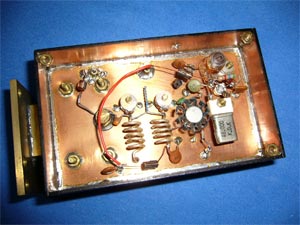
10GHz waveguide technics
Inspired by the book "Amateurfunkgeräte für das 10-GHz-Band" by Josef Reithofer (DL6MH), I started to build 10 GHz components based on gunplexers / waveguides. After, thanks to the company UKW-Technik in Baiersdorf, the procurement of WG-16 waveguide material also in small lengths was possible, I built various gunplexers as well as single-ended, push-pull and blow-through mixers. Gunn diodes from Valvo or Microwave-Associates were used in the oscillators. Mixer diodes of type 1N23 or 1N415 were used in the mixers. These parts could be purchased, at affordable prices, only at flea markets. The following pictures give an impression of this nostalgic technology.
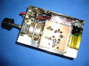
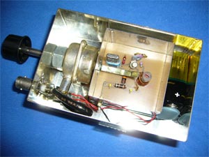
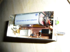
test oscillator with attenuator
In the "UHF-Unterlagen" Volume I/II by Karl Weiner (DJ9HO) a fixed signal generator for RX alignment up to 5.67 GHz is described by Michael Kuhne (DB6NT). The oscillator oscillates at 28.8MHz and the output signal can be attenuated to inaudibility by a built-in attenuator (Preh 0-1 GHz capable).
DCF77 evaluation board
In the "Praxisheft 2" of the AATiS the circuit of a time signal receiver DCF77 by Helmut Pape (DK2ZA) is described. This circuit, which is built on a Euro-board, is ideal to understand the technology of time signal transmissions and to fathom it with own experiments.
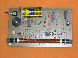
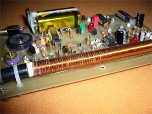
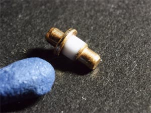
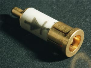
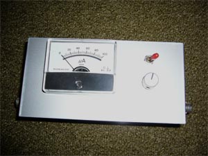
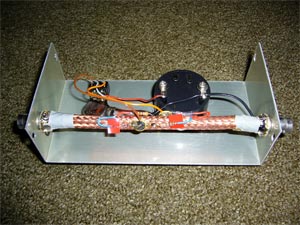
reflectometer
Also in the "UHF-Unterlagen" Volume I/II by Karl Weiner (DJ9HO) a SWR meter (reflectometer)is described, whose coupling element consists of a piece of coaxial cable, into which two coupling loops are pulled. This SWR meter can still be used up to the 23cm range.
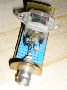
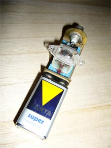
RF sniffer
A rectifier diode and a small amplifier are mounted on a brass bracket. This small tool can be used for the detection of high frequency.
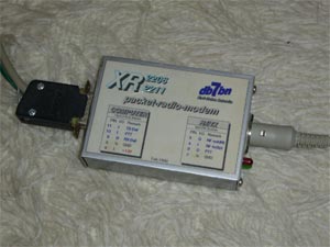
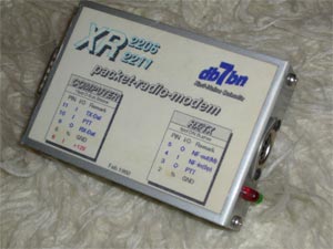
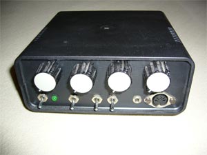
BayCom packet radio 1k2 modem
With the advent of PacketRadio in amateur radio, the BayCom group was formed. This 1k2 modem was first operated with a C-64 computer and later with a PC under DOS.
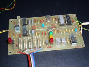
RTTY filter converter
This RTTY filter converter is based on the technique of operational amplifiers. Turning potentiometers, which are switched over by a step switch, are provided for the different shelves. A variable shift is made possible by the external helical potentiometer. With the toggle switch the shift position can be switched from normal to reverse. The converter is designed for connection to a C-64 user port.
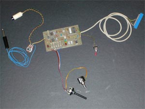
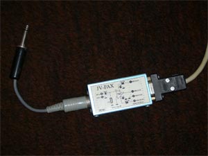
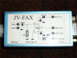
SSTV modem
The following OP741 based comparator is the only hardware to decode FAX or SSTV with programs like JV-FAX.
80m foxhunting receiver
I built the kit of the 80m foxhunting receiver to participate in the DARC E29 OV fox hunts.
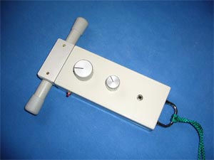
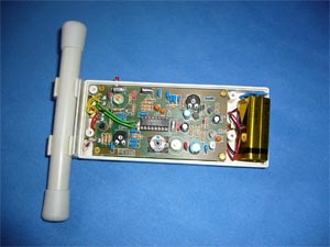
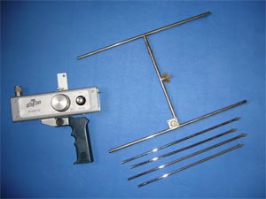
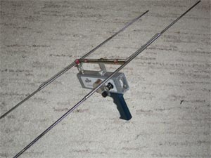
144MHz foxhunting receiver
I bought this 2m direction finder receiver at a flea market for 5,-DM. After the necessary restoration I participated with it in OV fox hunts in the district Hamburg and Schleswig-Holstein. (but always according to the motto "to be there is more important than to win").
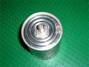
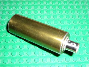
dummy load
A 50 ohm terminating resistor is important for alignment work on transmitter stages. The following pictures show two different models. The left one has a built-in rectifier diode, which allows relative power measurements up to 10Watt at 430MHz. An empty condensed milk can serves as housing. The right model consists of a resistor network in a brass tube. The tube is filled with thermal paste, which transfers the RF power converted into heat to the brass tube.
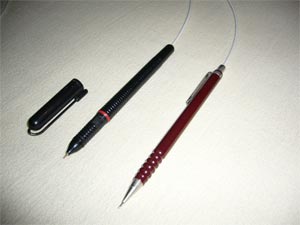
RF probe
From the "UHF-Unterlagen" Volume I/II by Karl Weiner (DJ9HO) comes the construction proposal for this RF probe. The electronics are built into a felt pen in the left model and into a mechanical pencil in the right model.
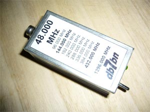
simple test oscillator
In a long discussion with Klaus (DL2HAD) the idea arose to build a simple test oscillator for 48MHz with an oscillator assembly from computer technology. The harmonics are ideal for measurement purposes at 144MHz and 432MHz.
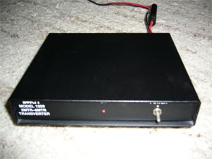
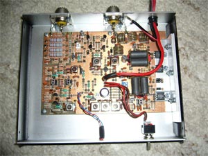
TenTec 50MHz transverter
With the release of the 50MHz band for amateur radio, the company TenTec has brought a 6m transverter on the market, which I bought as a kit and built. Unfortunately I drew a blank at the "lottery" of the 6m licenses.
analogue AF notch filter
Based on OP741 operational amplifiers a AF filter was described in the December 1997 issue of the magazine "funk". This technology can certainly not keep up with today's DSP technology, but my device still does its job on a FRG-7000.
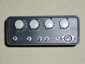
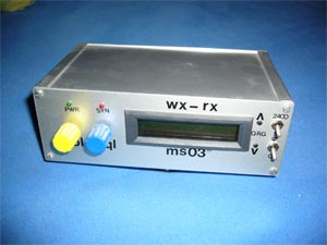
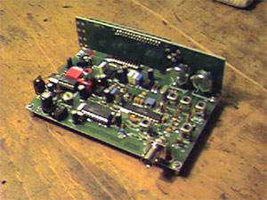
weather RX
Through the initiative of Hein (DL6LAY), 5 weather receivers were set up in winter 2002/2003 at our DARC chapter. With the help of the appropriate software weather pictures can be received, represented and evaluated over the sounding map. Further information can be found on the website of the DARC club M21.
SDR Softrock evaluation board
Inspired by a lecture about "Software Define Radio" I found the experimental board SoftRock5 at the American QRP group. With this small board the SDR possibilities on 40m and 20m can be tested well. The first impression with simple software like Rocky was convincing. This is clearly the Zunkunft in the receiver technology.
paddle
At the HamRadio 2008 I bought the kit of a Kent Squeeze Paddle. The following pictures show step by step the different stages of the assembly.
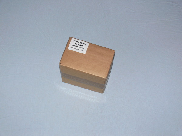
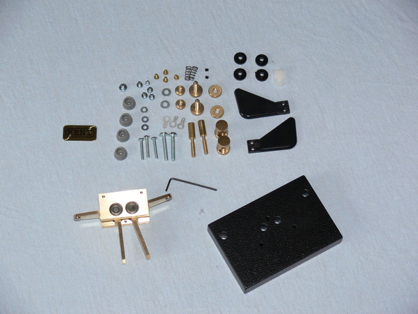
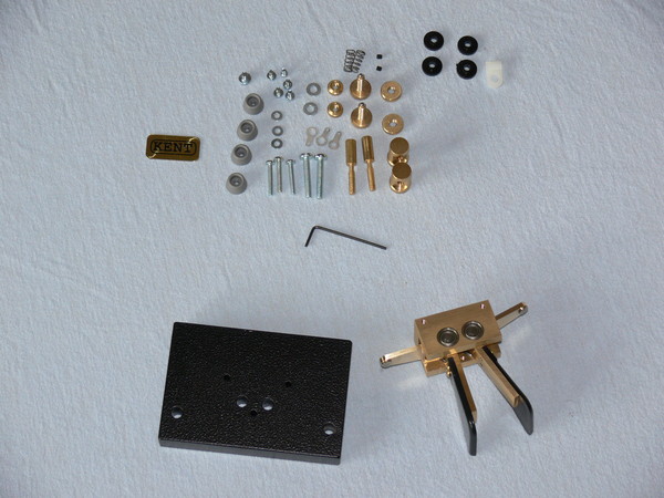
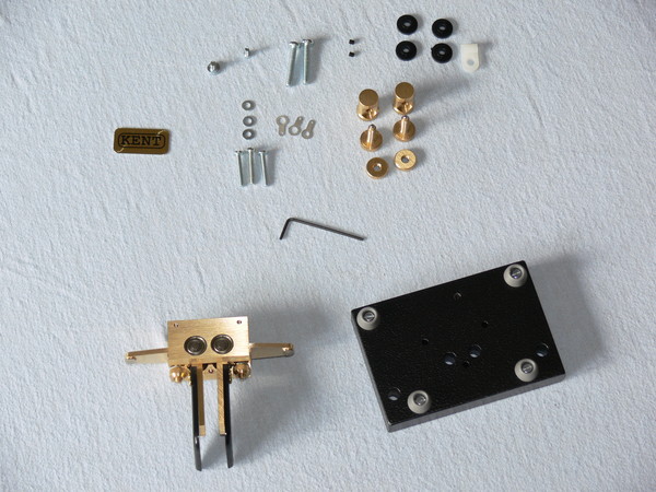
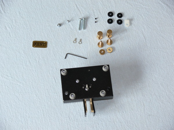
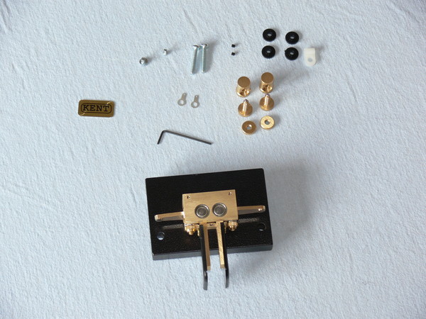
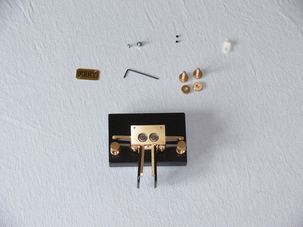
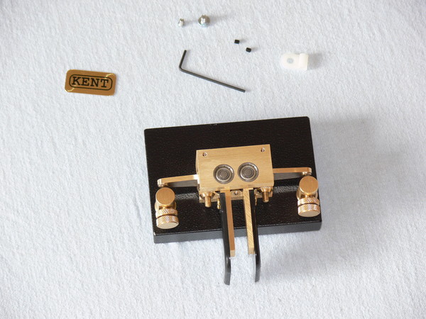
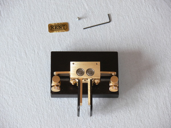
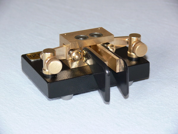
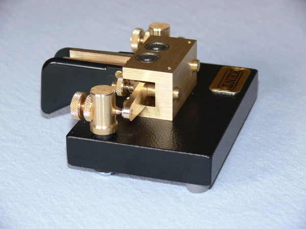
Click on the photos to zoom them!
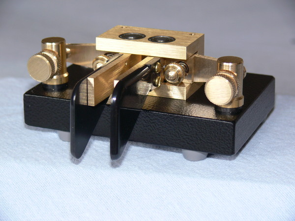
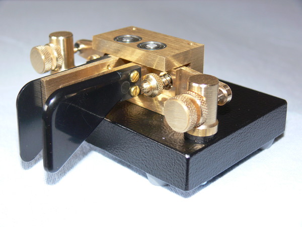
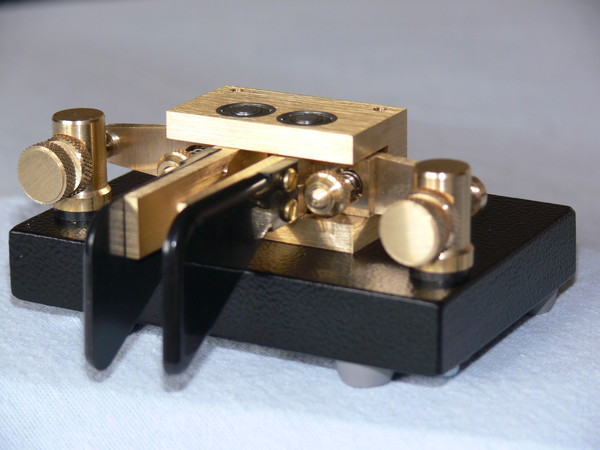
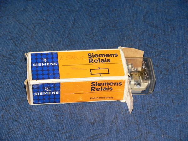
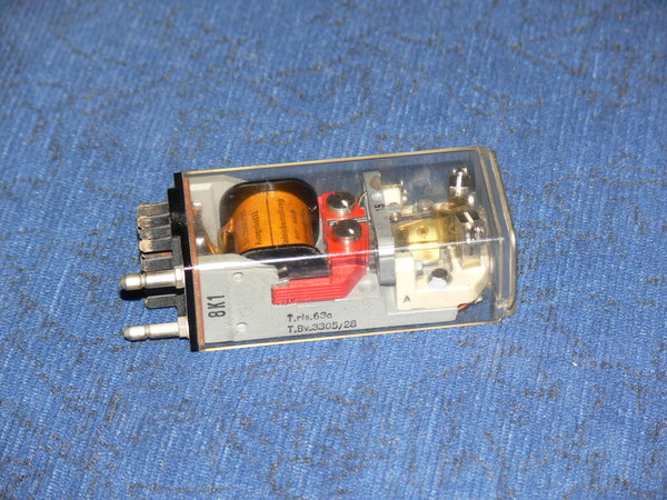
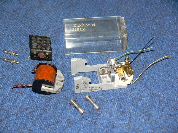
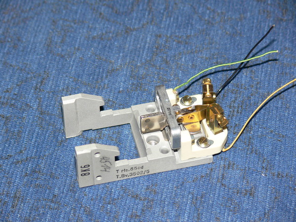
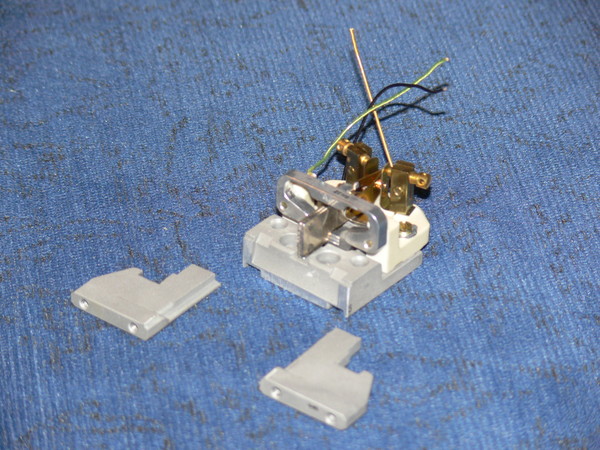
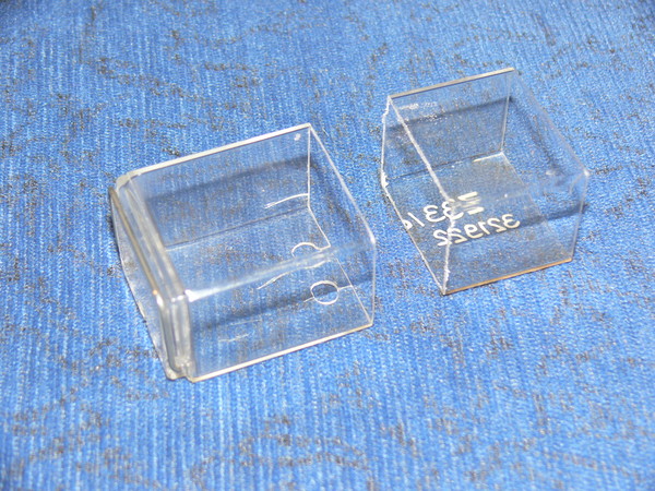
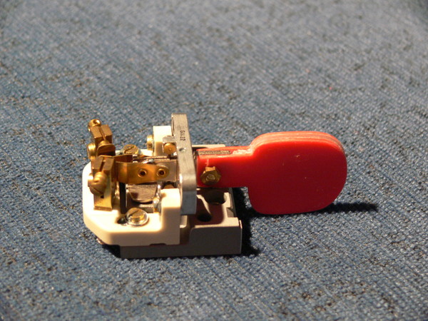
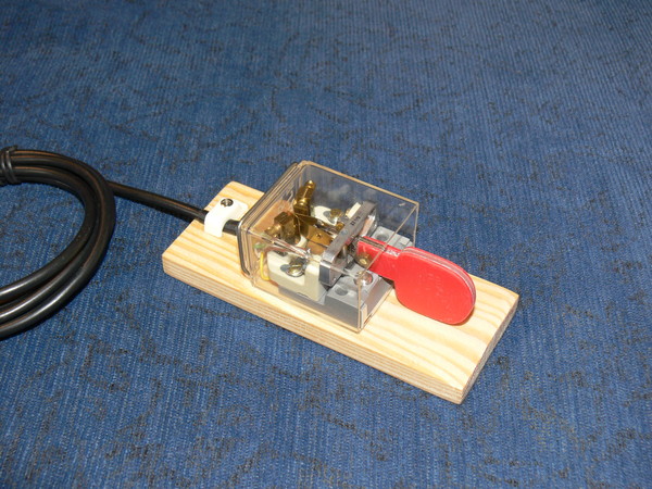
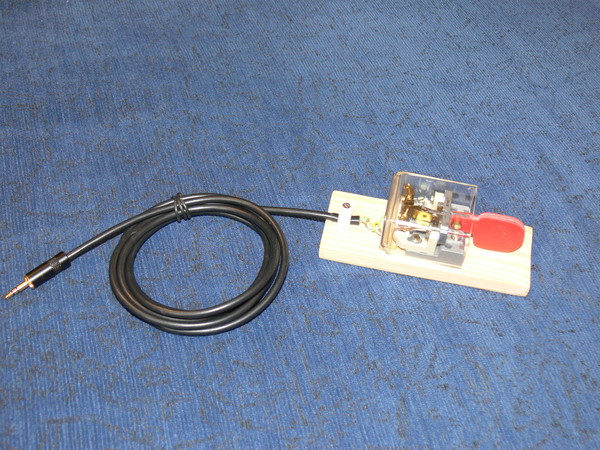
telegraph relais paddle
The following photos show how to build a paddle from a Siemens telegraph relay.
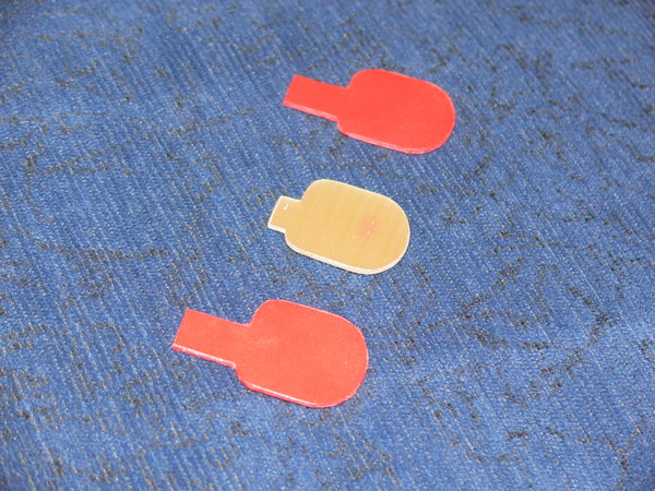
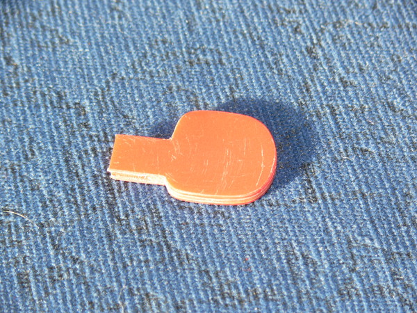
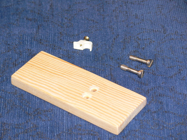
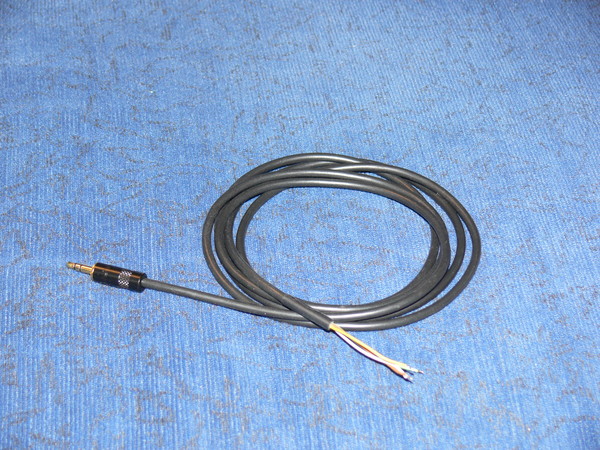
Click on the photos to zoom them!
soundcard interface
To avoid hum loops between the computer and the radio, galvanic isolation is required. The easiest way to achieve this is to use two AF transformers. The following picture shows the setup with two transformers and a level adjustment.
The interface can be used for all digital transmission modes.
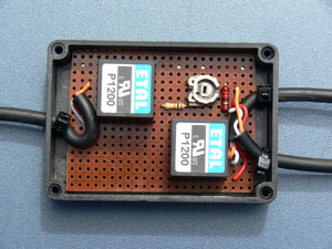
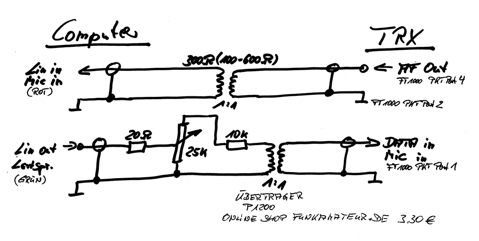
Click on the schematic to enlarge it!
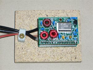
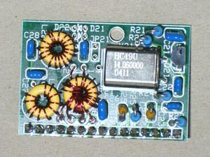
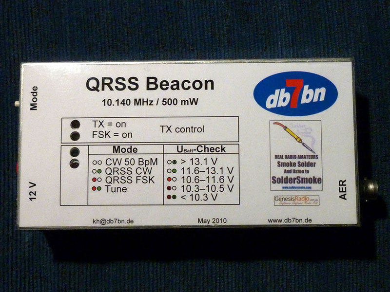
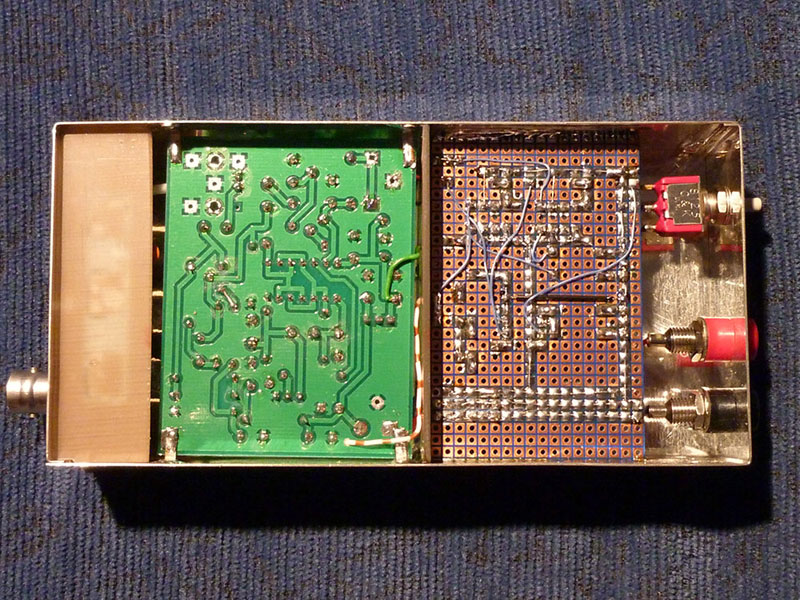
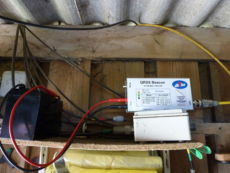
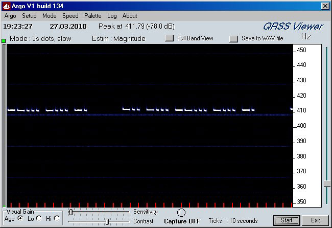
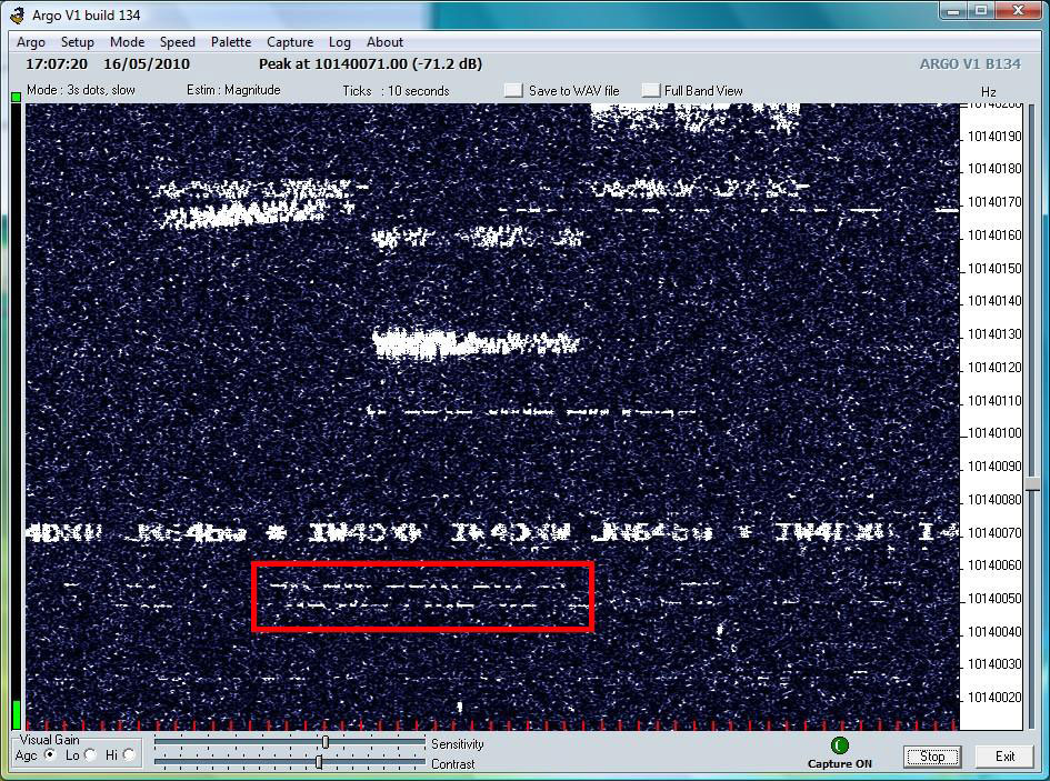
QRSS beacon
Inspired by a Soldersmoke Podcast I build a QRSS Beacon. The meaning of QRS is „Send slower“ and based on this QRSS signifies very slow speed CW. In this case a dit needs 1 second and a dah 3 seconds. To key the callsign DB/BN you need about 1 minute. The beacon consists of 3 main units: the CW controller based on a AVR Atmel ATTiny45, the transmitter kit Genesis Q5 and a low pass filter. The beacon can transmit in CW and FSK and can produce 500mW Output on 10,140 MHz.
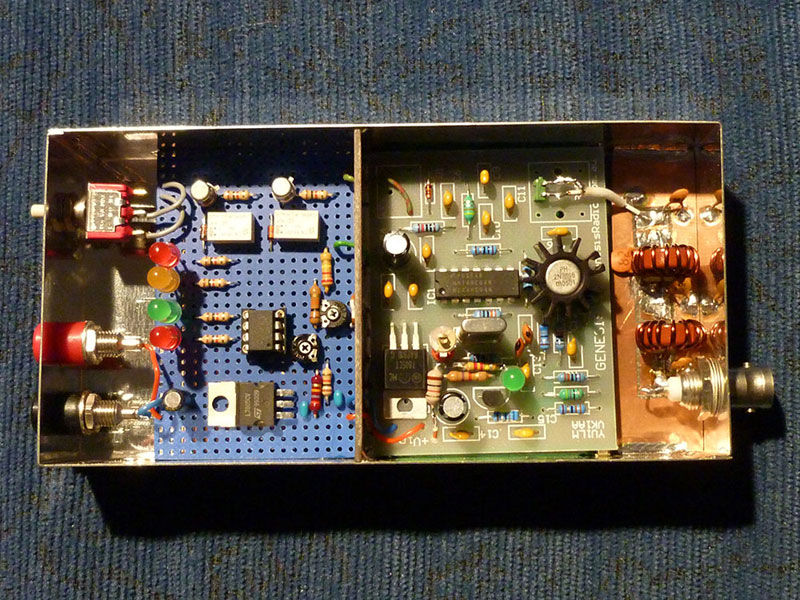
Click on the photos to zoom them!